Views: 377
Deployment Methods
- One-armed Deployment
- Two-armed Deployment
- nPath or Direct Server Response (DSR) Deployment
One-Arm Deployment
In one-arm deployment, the load balancer is not physically in line of the traffic, which means that the load balancer’s ingress and egress traffic goes through the same network interface. Traffic from the client through the load balancer is network address translated (NAT) with the load balancer as its source address. The nodes send their return traffic to the load balancer before being passed back to the client. Without this reverse packet flow, return traffic would try to reach the client directly, causing connections to fail.
In a one-armed topology, the virtual server is on the same subnet and VLAN as the pool members.
Source address translation must be used in this configuration to ensure that server response traffic returns to the client by way of BIG-IP LTM. Since the servers do not have the load balancers as the gateway we need to use SNAT for the servers to talk back to the LTM or it could cause assymetric routing problem.
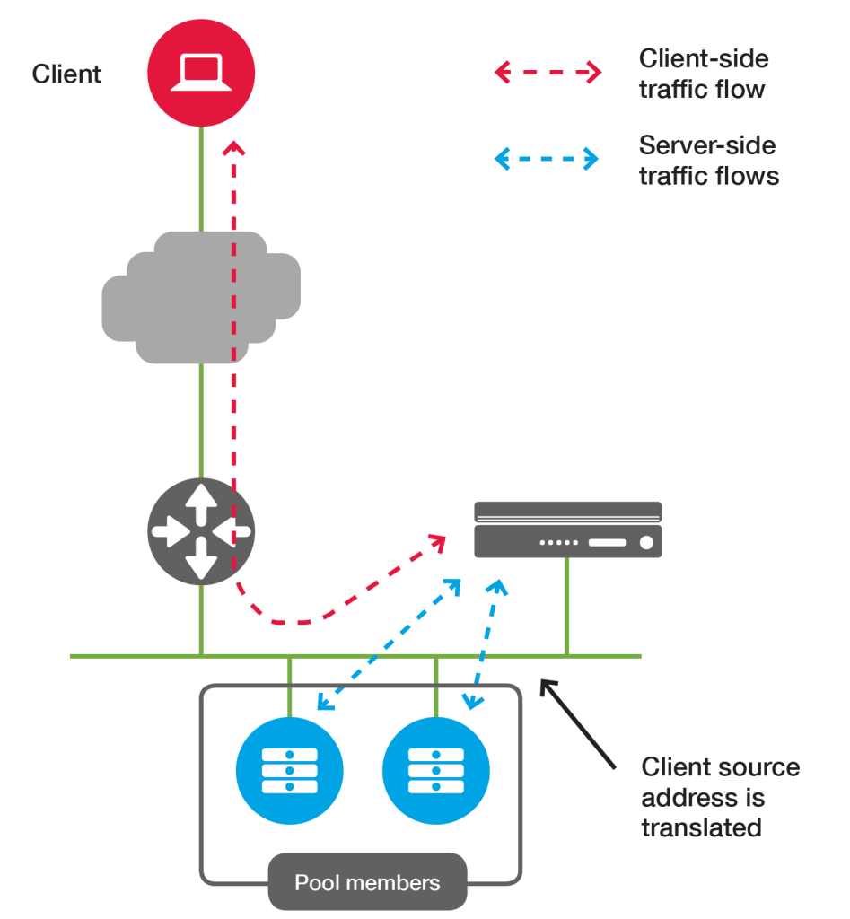
Some advantages of One-armed topology,
- Allows for rapid deployment.
- Requires minimal change to network architecture to implement.
- Allows for full use of BIG-IP LTM feature set.
- Does not allow asymmetrical routing of server traffic. Because the system translates the source address, the client IP address is not visible to pool members. (You can change this for HTTP traffic by using the X-Forwarded-For header).
Two-armed Deployment
In a multi-arm configuration, the traffic is routed through the load balancer. The end devices typically have the load balancer as their default gateway.
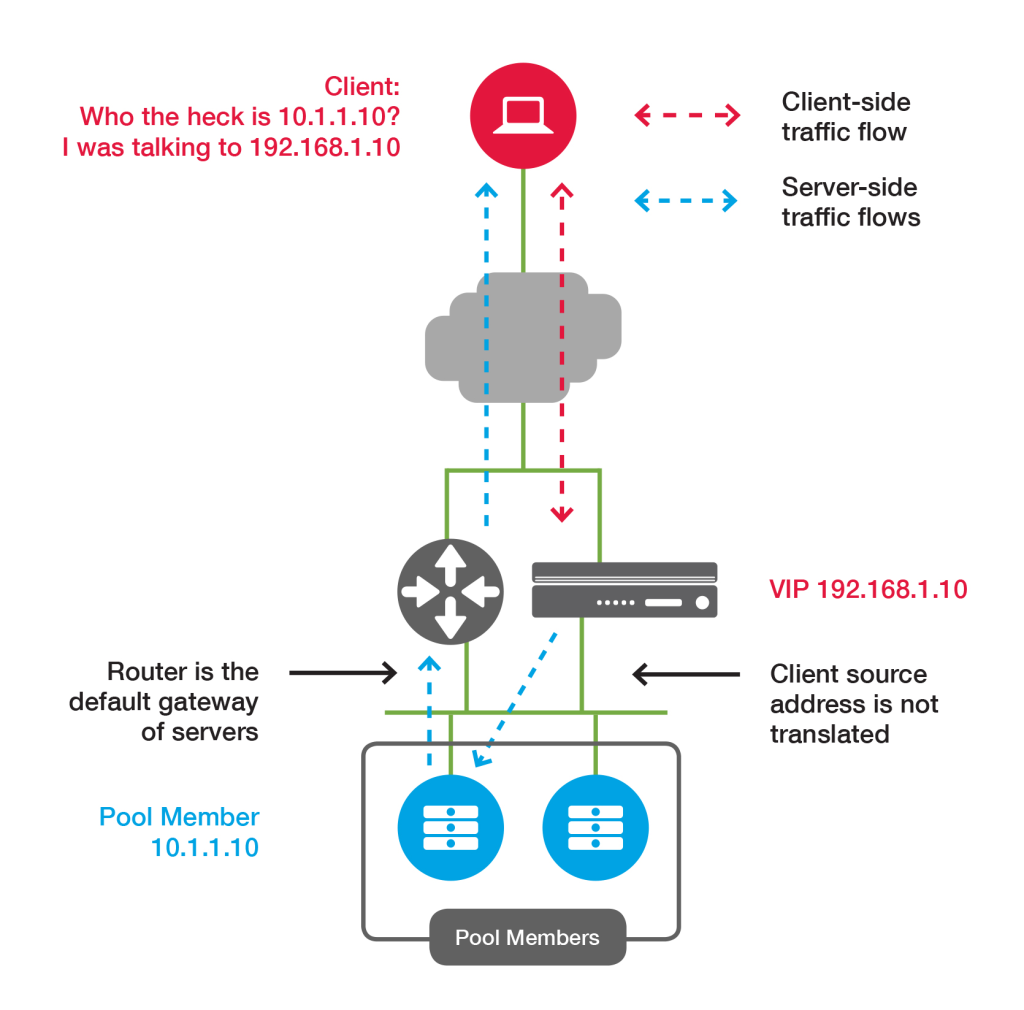
n the two-armed topology, the virtual server is on a different VLAN from the pool members. The BIG-IP system routes traffic between them.
Source address translation may or may not be required, depending on overall network architecture. If the network is designed so that pool member traffic is routed back to BIG-IP LTM, it is not necessary to use source address translation.
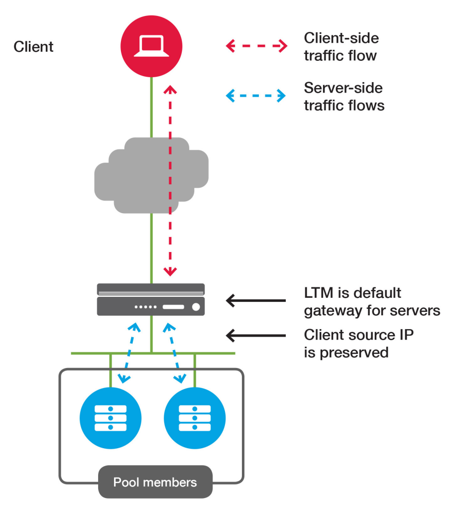
Source address translation in a two-armed topology
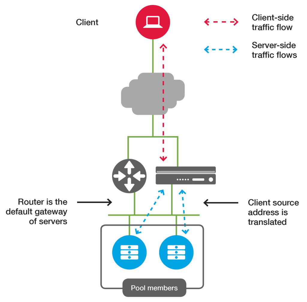
If pool member traffic is not routed back to BIG-IP LTM, it is necessary to use source address translation to ensure it is translated back to the virtual server IP.
The following figure shows a two-armed deployment without source address translation:
The following figure shows the same deployment with source address translation:
Two-armed topology benefits
- Allows preservation of client source IP.
- Allows for full use of BIG-IP LTM feature set.
- Allows BIG-IP LTM to protect pool members from external exploitation.
- May require network topology changes to ensure return traffic traverses BIG-IP LTM.
nPath (DSR) Deployment
In the nPath or direct server return (DSR) topology, return traffic from pool members is sent directly to clients without first traversing the BIG-IP LTM. This allows for higher theoretical throughput because BIG-IP LTM only manages the incoming traffic and does not process the outgoing traffic.
This deployment significantly reduces the available BIG-IP LTM features.
Direct Server Return (DSR) load balancer
DSR builds on the passthrough load balancer. DSR is an optimization in which only ingress/request packets traverse the load balancer. Egress/response packets travel around the load balancer directly back to the client. The primary reason why it’s interesting to perform DSR is that in many workloads, response traffic dwarfs request traffic (e.g., typical HTTP request/response patterns). Assuming 10% of traffic is request traffic and 90% of traffic is response traffic, if DSR is being used a load balancer with 1/10 of the capacity can meet the needs of the system. Since historically load balancers have been extremely expensive, this type of optimization can have substantial implications on system cost and reliability (less is always better).
DSR load balancers extend the concepts of the passthrough load balancer with the following:
- The load balancer still typically performs partial connection tracking. Since response packets do not traverse the load balancer, the load balancer will not be aware of the complete TCP connection state. However, the load balancer can strongly infer the state by looking at the client packets and using various types of idle timeouts.
- Instead of NAT, the load balancer will typically use Generic Routing Encapsulation (GRE) to encapsulate the IP packets being sent from the load balancer to the backend. Thus, when the backend receives the encapsulated packet, it can decapsulate it and know the original IP address and TCP port of the client. This allows the backend to respond directly to the client without the response packets flowing through the load balancer.
- An important part of the DSR load balancer is that the backend participates in the load balancing. The backend needs to have a properly configured GRE tunnel and depending on the low level details of the network setup may need its own connection tracking, NAT, etc.
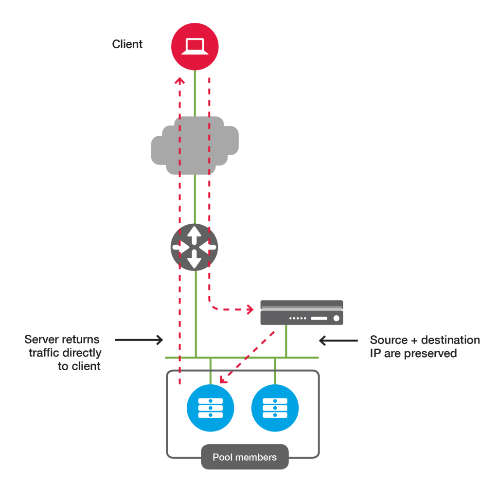
nPath topology details
- Allows maximum theoretical throughput.
- Preserves client IP addresses to pool members.
- Limits availability of usable features of BIG-IP LTM and other modules.
- Requires modification of pool members and network.
- Requires more complex troubleshooting.


